What Is a Lock-Up Valve?
A lock-up valve is a pneumatic accessory used to protect the operating position of a pneumatic actuator when the instrument air supply or control air signal becomes abnormal.
In a typical control valve assembly, the actuator depends on compressed air to maintain or change valve position. If the air supply suddenly falls below a defined pressure, simply losing the air can cause the actuator to move to an undesired position.
A lock-up valve provides another option.
Depending on its configuration, it can retain actuator pressure, shut off the pneumatic circuit, switch the air path, or lock the control valve in its last position.
This makes lock-up valves useful in process control applications where an unexpected change in valve position could affect production, equipment or process stability.
Different manufacturers use different pneumatic designs. SMC, KOSO, Fisher and Masoneilan all offer solutions for air-failure or lock-up functions, but their structures and operating methods are not identical.
How Does a Lock-Up Valve Work?
The basic principle is based on monitoring pneumatic pressure.
Under normal conditions, the instrument air supply passes through the lock-up device and reaches the actuator or pneumatic control circuit.
When the monitored pressure remains above the preset value, the valve stays in its normal operating state.
When the pressure falls below the setpoint, the internal mechanism changes the pneumatic circuit.
Depending on the design, this may:
- Shut off the air passage
- Trap pressure inside the actuator
- Switch the air supply to another port
- Exhaust or redirect actuator pressure
- Keep the actuator in its current position
The important point is that a lock-up valve does not normally control the process medium directly. Instead, it controls the pneumatic circuit connected to the actuator.
SMC Lock-Up Valve Working Principle
SMC's IL201/211/220 Series Lock-Up Valves are designed for pneumatic process control systems where an air-source or air-supply piping failure occurs.
The series includes single-acting, double-acting and three-port configurations. SMC states that the single- and double-acting versions retain pressure at the operating section as an emergency measure until the air source returns to normal, while the three-port version changes the supply port when a problem occurs.
The operating principle is based on the relationship between signal pressure and an adjustment spring.
When the signal pressure is higher than the spring setting, the diaphragm moves, the exhaust passage closes and air is directed into the lower diaphragm chamber. This moves the internal piston and opens the normal air passage.
When signal pressure falls below the set pressure, the diaphragm position changes. Pressure in the lower chamber is released, and the spring moves the valve mechanism to shut off the relevant air circuit. In the three-port configuration, the flow path changes from one supply port to another.
For the IL201/211/220 series, SMC lists a set-pressure range of 0.14–0.7 MPa and a maximum shut-off pneumatic circuit pressure of 0.7 MPa.
A key consideration is clean instrument air. SMC's manual specifically recommends clean compressed air with moisture and dust removed because the internal construction includes small passages.
KOSO Lock-Up Valve Working Principle
KOSO uses lock valves as pneumatic accessories for shutoff, switching or locking of an instrumental air circuit.
The KOSO CL420 and CL523 Lock Valves are examples of this type of pneumatic control accessory. KOSO lists a maximum pressure of 800 kPa and a set-pressure range of 100–600 kPa for these models.
The basic operating concept is to monitor the relevant pneumatic pressure and change the air circuit when the pressure reaches the specified switching condition.
In a control valve assembly, this function can be used to prevent uncontrolled actuator movement following an abnormal air-supply condition.
The exact pneumatic connections and switching behavior depend on the selected model and actuator arrangement. Therefore, when replacing a KOSO lock valve, the supplier should check the original model, port configuration, actuator type, normal supply pressure and required failure function rather than selecting a replacement only by connection size.
Fisher Lock-Up Valve Working Principle
Fisher approaches the function through pressure-sensing trip valves.
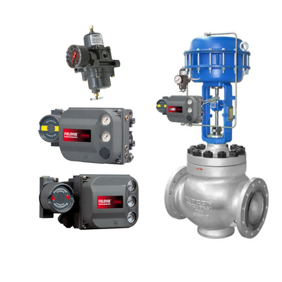
The Fisher 377 Pressure-Sensing Trip Valve is designed for applications where a specific actuator action is required when supply pressure falls below an adjustable trip point.
When supply pressure falls below the trip point, the 377 can be configured to make the actuator:
- Fail up
- Lock in the last position
- Fail down
When supply pressure rises above the trip point, the trip valve automatically resets and allows the system to return to normal operation.
For a lock-in-last configuration, the basic idea is to isolate the actuator's pneumatic output so that the pressure already acting on the actuator is retained.
This is different from simply venting the actuator.
Instead of immediately forcing the actuator toward a spring-fail position, the pneumatic circuit is configured to preserve the actuator's existing condition until the air supply recovers.
Fisher also provides application arrangements using the 377 trip valve with digital valve controllers and pneumatic actuators for lock-in-last functions.
This makes the Fisher solution particularly relevant to control valve assemblies where maintaining the existing valve position during a loss of supply pressure is part of the required failure philosophy.
Masoneilan Lock-Up Valve Working Principle
Masoneilan provides pneumatic air lock-up and transfer valve solutions for control valve applications.
One example is the Masoneilan 78-80 Transfer Valve. According to Baker Hughes documentation, the transfer valve switches airflow from one port to another when the signal pressure falls below the preset pressure during an air failure.
The three-way transfer valve can also be used as a lock-up valve by plugging the exhaust port. In this configuration, the valve can lock the control valve in its last position by confining air pressure in the actuator. When the failed air pressure recovers above the set pressure, the locked condition is released and the control valve returns to normal operation.
Masoneilan also lists the 77-6 Air Lock-up Valve in its product documentation and resource center.
The key concept is therefore similar to Fisher's lock-in-last arrangement: rather than allowing the actuator pressure to escape immediately, the lock-up device isolates the pneumatic circuit and maintains the actuator condition during the air-failure period.
SMC vs KOSO vs Fisher vs Masoneilan
Although all four brands can be associated with pneumatic lock-up functions, their product structures should not be treated as interchangeable.
| Brand |
Typical Product |
Main Function |
Operating Concept |
| SMC |
IL201/211/220 |
Pneumatic lock-up |
Pressure sensing and pneumatic circuit shutoff/switching |
| KOSO |
CL420 / CL523 |
Instrument air circuit lock/switch |
Pneumatic pressure-based circuit switching |
| Fisher |
377 |
Pressure-sensing trip |
Fail-up, fail-down or lock-in-last |
| Masoneilan |
78-80 / 77-6 |
Transfer / air lock-up |
Air-path switching or actuator pressure retention |
The biggest difference is not simply the brand. It is the required failure action.
For example, one control valve may need to remain in its current position when air pressure is lost, while another may need to move fully open or fully closed.
Therefore, the lock-up valve must be selected together with the actuator and control valve failure philosophy.
What Happens When Instrument Air Pressure Falls?
A typical lock-up sequence can be understood in four steps:
Step 1: Normal Operation
Instrument air pressure is above the lock-up setting.
The pneumatic circuit operates normally, and the actuator responds to the positioner's output.
Step 2: Air Pressure Drops
The lock-up valve senses that the monitored pressure has fallen below its preset value.
Step 3: Pneumatic Circuit Changes
The internal mechanism switches, shuts off or isolates the relevant air passage.
The exact action depends on the model and configuration.
Step 4: Actuator Position Is Controlled
The actuator either retains its pneumatic pressure, locks its current position or follows the specified fail action.
When normal air pressure is restored, some designs automatically reset and return the pneumatic circuit to normal operation.
How to Select a Lock-Up Valve
When selecting or replacing a lock-up valve, the brand name alone is not enough.
Check the following information:
1. Actuator type
Single-acting and double-acting actuators require different pneumatic arrangements.
2. Required failure action
Determine whether the valve needs:
- Fail open
- Fail closed
- Fail in place
3. Supply pressure
Check normal, minimum and maximum instrument air pressure.
4. Trip or set pressure
The lock-up pressure must correspond to the actual pneumatic system requirements.
5. Port configuration
Check the number of ports, connection type and pneumatic flow path.
6. Positioner configuration
The lock-up valve must be compatible with the positioner and actuator arrangement.
7. Response requirements
For critical control applications, the switching and pressure-retention behavior should be considered during system design.
Common Problems With Lock-Up Valves
Several problems can affect lock-up valve performance.
Incorrect Set Pressure
If the setting is too high, the lock-up valve may activate during normal pressure fluctuations. If it is too low, the system may not respond as intended during an actual air-supply failure.
Contaminated Instrument Air
Moisture, dust and other contaminants can affect small pneumatic passages and internal components. Clean instrument air is especially important for compact pneumatic lock-up devices.
Incorrect Pneumatic Connection
A lock-up valve may function correctly by itself but fail to provide the required actuator action if the tubing arrangement is incorrect.
Wrong Failure Mode
A lock-in-last arrangement should not be assumed to be equivalent to fail-open or fail-closed operation. The required failure action must be defined before selecting the pneumatic circuit.
Improper Replacement
Different manufacturers may use different internal structures even when their products perform similar functions. Model-to-model replacement should therefore be verified using the original pneumatic schematic and actuator requirements.
Conclusion
SMC, KOSO, Fisher and Masoneilan all provide pneumatic solutions that can be used for lock-up, air-failure protection or pneumatic circuit switching, but their operating mechanisms and product configurations differ.
SMC IL Series products use pressure sensing and diaphragm-based pneumatic switching. KOSO CL Series lock valves are used for instrumental air circuit shutoff, switching and locking. Fisher 377 uses pressure sensing to provide configurable fail-up, fail-down or lock-in-last functions. Masoneilan solutions such as the 78-80 transfer valve can switch pneumatic flow and, in a suitable configuration, retain actuator pressure to lock a control valve in its last position.
For procurement and replacement, the most important factors are actuator type, required failure position, supply pressure, trip pressure, port configuration and pneumatic connection.
If you are sourcing SMC, KOSO, Fisher or Masoneilan lock-up valves, providing the original model number and actuator/positioner configuration is the most reliable way to identify a suitable replacement or complete control valve accessory package.


 Uw bericht moet tussen de 20-3.000 tekens bevatten!