Wat is het fail-safe in de regelklep?
Controleklep Faalveilig ontwerp: de hoeksteen van industriële processtabiliteit en personeelveiligheid
Abstract
In moderne industriële automatisering dienen regelkleppen als de uiteindelijke besturingselementen, 承担 de kritieke verantwoordelijkheid om belangrijke procesparameters precies te reguleren, zoals vloeistofdebiet, druk, temperatuur en vloeistofniveau. Elk systeem kan echter plotselinge mislukkingen tegenkomen, en op dergelijke momenten wordt het "faalveilige" ontwerp van regelkleppen het kernverdedigingsmechanisme dat de continuïteit van industriële processen, integriteit van apparatuur en zelfs personeelsveiligheid zorgt. Dit artikel zal een deskundige analyse van de definitie, classificatie, implementatiemechanismen en applicatiestrategieën van controleklep-faalveilig ontwerp in verschillende industriële scenario's bieden. Het zal ook onderzoeken hoe geavanceerde foutdiagnosetechnologieën de betrouwbaarheid van regelkleppen verbeteren, waardoor de Xiangjing Company naadloos wordt geïntegreerd (www.shgongboshi.com) Uitstekende bijdragen en innovatieve oplossingen op dit gebied. Het doel is om de industriële sector uitgebreide en diepgaande inzichten te bieden om veiliger en efficiëntere geautomatiseerde systemen te helpen bouwen.
Invoering
In de steeds meer complexe industriële productieomgevingen van vandaag speelt automatiseringstechnologie een cruciale rol. Onder deze technologieën dienen controlekleppen als het "hart" van industriële processen, met hun prestatiestabiliteit en betrouwbaarheid die de productie -efficiëntie, productkwaliteit, energieverbruik en kritische veiligheidsmaatregelen direct beïnvloeden.
Regelkleppen: het "hart" van industriële processen
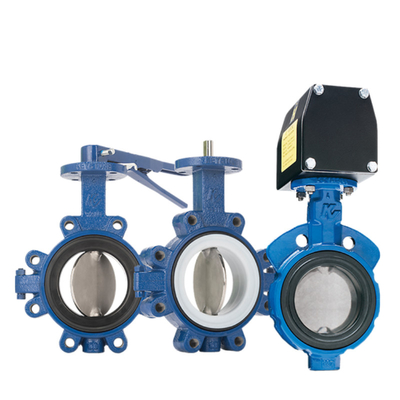
Aregelklepis een type klep dat vloeistofstroom reguleert door de grootte van de vloeistofdoorgang te veranderen. Het ontvangt signalen van een controller om de stroom direct te regelen en indirect procesvariabelen zoals druk, temperatuur en vloeistofniveau te beïnvloeden. In de terminologie van automatiseringscontrole,
regelkleppenworden aangeduid als "definitieve controle -elementen" en behoren tot de meest gebruikte uiteindelijke controle -elementen in de moderne industrie. Juiste selectie en onderhoud van regelkleppen zijn van cruciaal belang voor het verbeteren van de efficiëntie, veiligheid, winstgevendheid en milieubescherming.
In procesbesturingslussen bestaan moderne fabrieken uit honderden of zelfs duizenden controlelussen die onderling zijn verbonden om ervoor te zorgen dat kritische procesvariabelen (zoals druk, stroom, niveau en temperatuur) binnen het vereiste bereik blijven, waardoor de kwaliteit van het eindproduct wordt garandeerd.
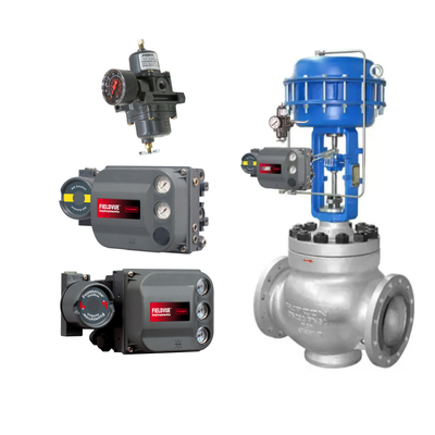
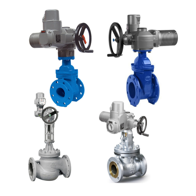
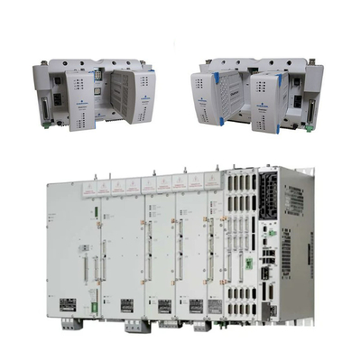
Regelkleppen vormen de kern van deze lussen, verantwoordelijk voor het reguleren van de vloeistofstroom (zoals gas, stoom, water of chemische mengsels) om belastingstoringen te compenseren en de gecontroleerde procesvariabelen zo dicht mogelijk bij het setpoint te houden. A complete control valve assembly typically consists of a valve body (containing fluid passages and regulating elements), valve internals (such as valve discs, valve plates, valve seats, valve cores, etc., which directly contact the fluid and regulate flow), an actuator (providing the driving force required to operate the valve), and various valve accessories (such as positioners, converters, supply pressure regulators, limit switches, enz.).
Fail-Safe: de hoogste prioriteit in industrieel ontwerp
Op het gebied van industriële automatisering is alleen het bereiken van functionele controle onvoldoende; Het is ook noodzakelijk om het gedrag van het systeem te overwegen onder abnormale omstandigheden, dwz "faalveilig" ontwerp. Fail-safe verwijst naar het systeem dat automatisch een vooraf gedefinieerde, niet-gevaarlijke toestand invoert wanneer een fout optreedt of het aandrijfvermogen verloren gaat, waardoor ongevallen worden voorkomen of verzachten.
Fail-safe ontwerp voor regelkleppen is een onmisbaar onderdeel van de industriële productie, met name bij de productie en verwerking van hoogwaardige, gevaarlijke materialen zoals ruwe olie, aardgas en chemicaliën. Het voorkomt effectief belangrijke ongevallen, zoals in brandstofpijpleidingen, waar de afsluitingskleppen van de veiligheid automatisch sluiten bij het detecteren van onveilige omstandigheden, waardoor brandstof de verbrandingskamer binnenkomt en daardoor branden of explosies vermijdt. Bovendien, door het systeem onmiddellijk naar een veilige staat te leiden, kunnen economische verliezen veroorzaakt door schade aan apparatuur en productieonderbrekingen worden geminimaliseerd. Wat nog belangrijker is, faalveilige mechanismen beschermen operators rechtstreeks tegen potentiële gevaren, wat de meest fundamentele overweging is in alle industriële ontwerpen. Bovendien hebben veel industrieën strikte veiligheidsvoorschriften en normen (zoals SIL-beoordelingen) die kritieke apparatuur vereisen om specifieke fail-safe-mogelijkheden te bezitten, waardoor faalveilig ontwerp een noodzakelijke voorwaarde is voor de naleving van de voorschriften.
Xiangjing Company begrijpt het belang van fail-safe ontwerp voor regelkleppen volledig en streeft ernaar om producten met een hoge betrouwbaarheidscontroleklep te leveren en oplossingen die voldoen aan internationale veiligheidsnormen. Door continue technologische innovatie en strikte kwaliteitscontrole wil Xiangjing een vertrouwde partner worden in het opbouwen van een veilige en efficiënte industriële toekomst. Ga voor meer informatie naarDe officiële website van Xiangjing Company.

Deel één: Fundamentals of Control Valve Fail-Safe
Deze sectie zal de kernconcepten van de controleklep falenveilig onderzoeken, inclusief de precieze definitie ervan, de cruciale rol in de industriële veiligheid en zijn relatie met internationale veiligheidsnormen (zoals SIL).
1. Wat is de regelklep faalveilig?
Regelklep Fail-Safe verwijst naar de automatische beweging van het afsluitselement van de klep naar een vooraf bepaalde positie wanneer de aandrijfvervoerder wordt onderbroken (bijv. Fout van instrumentluchtvoeding, stroomuitval). Deze vooraf ingestelde positie moet de "veilige" toestand zijn die nodig is om het proces en de apparatuur te beschermen. Het is een inherent kenmerk dat is ontworpen om niet -geplande afsluitingen of systeemafwijkingen aan te pakken.
Fail-Safe Design is een kerncomponent van functionele veiligheid, met als doel het verminderen van risico's voor personeel, de omgeving en eigendom tot een acceptabel niveau. In een reactor, als het koelsysteem bijvoorbeeld faalt, moet de koelwaterventiel automatisch openen om oververhitting en potentiële gevaren te voorkomen. Omgekeerd, als de brandstoftoevoerklep niet wordt gesloten tijdens een fout, kan dit leiden tot continue brandstoflekkage, wat leidt tot brand of explosie.
Tijdige overgang naar een veilige toestand voorkomt dat apparatuur onder foutomstandigheden blijft werken en schade veroorzaakt. Het belangrijkste is dat fail-safe mechanismen de risico's waarmee operators worden geconfronteerd rechtstreeks vermindert.
Fail-safe ontwerp is nauw verwant aan SIL (veiligheidsintegriteitsniveau). SIL is een discrete beoordeling die wordt gebruikt om de betrouwbaarheid van veiligheidsfuncties te meten en de mate van risicoreductie te kwantificeren. Een enkele component (zoals een regelklep) kan geen SIL -beoordeling op zichzelf hebben; Alleen een complete veiligheidslus- of veiligheidsinstrumentensysteem (SIS) kan een SIL -beoordeling bereiken. Een typische veiligheidslus omvat sensoren, evaluatie- en uitgangseenheden (zoals een veiligheid PLC) en geautomatiseerde proceskleppen (inclusief solenoïde kleppen, actuatoren en proceskleppen). Het faalveilige ontwerp van regelkleppen is een kritieke component bij het behalen van een specifieke SIL-beoordeling, zodat veiligheidsfuncties betrouwbaar kunnen worden uitgevoerd in modi met lage aanvraag (waarbij het veiligheidssysteem niet meer dan eens per jaar wordt geactiveerd).
Fail-Safe Design is een kernaspect van risicobeheer. Traditionele besturingssystemen richten zich op efficiëntie en precisie onder "normale bedrijfsomstandigheden". De complexiteit en potentiële gevaren van industriële productie bepalen echter dat gedrag onder "abnormale omstandigheden" kritischer is. De essentie van faalveilige mechanismen is om te anticiperen op en slechtste scenario's tijdens de ontwerpfase te beperken en het systeem naar de "minst gevaarlijke" toestand te leiden. Dit is niet alleen een technische implementatie, maar een concrete toepassing van de veiligheidsfilosofie in engineering, die een paradigmaverschuiving weerspiegelt van 'productie -efficiëntie eerst' naar 'veiligheid eerst'. Dit betekent dat bij het selecteren van regelkleppen, hun fail-safe-modus niet alleen een technische parameter is, maar een strategische beslissing die wordt genomen na een grondige beoordeling en begrip van de risico's in het hele proces. Bij het aanschaffen en implementeren van controlekleppen moeten bedrijven prioriteit geven aan fail-safe-functionaliteit die even belangrijk is als prestaties, en in bepaalde kritieke toepassingen heeft veiligheid voorrang op alle andere overwegingen.
2. Classificatie en selectie van faalveilige modi
De faalveilige modi van regelkleppen zijn voornamelijk in drie typen gecategoriseerd, elk overeenkomend met specifieke toepassingsscenario's en veiligheidseisen. Het selecteren van de juiste fail-safe-modus is van cruciaal belang om de veilige werking van het systeem te waarborgen.
Fail-CLOSE (FC) / Air-Loss-Clasted (fail-closed)
Wanneer de aandrijfsenergie (zoals luchttoevoer of stroom) wordt onderbroken, beweegt het afsluitselement van de regelklep automatisch naar de gesloten positie. Dit betekent dat tijdens een fout de vloeibare doorgang is geblokkeerd. Deze modus wordt meestal bereikt via een veer-return-actuator, waarbij de voorlaadkracht van de veer de klep naar de gesloten positie duwt wanneer de luchtdruk of het vermogen verloren gaat.
Typische toepassingsscenario's zijn onder meer:
- Brandstofgaskleppen: in brandertoepassingen moeten de afsluitingskleppen van de veiligheid automatisch sluiten wanneer onveilige omstandigheden (zoals stroomuitval) worden gedetecteerd om te voorkomen dat brandstof (gas of olie) de verbrandingskamer binnengaat, waardoor brand of explosie wordt vermeden.
- Reactorvoerkleppen: in chemische reacties, als de reactie ongecontroleerd wordt (zoals een plotselinge toename van de temperatuur), moet de voedingsklep onmiddellijk dicht bij het stoppen van de materiaalinvoer, waardoor de reactie verder escaleert.
- Hogedruksystemen: in hogedrukvloeistoffen systemen voorkomt foutafsluiting per ongeluk lekkage van hogedrukmedia, waardoor het risico wordt verminderd.
Fail-open (fo) / verlies van druk-open (fail-open)
Wanneer het aandrijfvermogen wordt onderbroken, beweegt het stroomherstelelement van de regelklep automatisch naar de open positie. Dit betekent dat de vloeibare doorgang tijdens een storing volledig wordt geopend. Deze modus wordt ook vaak bereikt door actuatoren voor de voorjaar, maar de richting van de veerconfiguratie is tegengesteld aan de FC-modus, waardoor de klep tijdens een storing naar de open positie wordt geduwd.
Typische toepassingsscenario's zijn onder meer:
- Koelwaterkleppen: in reactoren of andere systemen die koeling vereisen, als het koelsysteem faalt of stroom wordt onderbroken, moet de koelwaterventiel automatisch openen om een continue stroom van het koelmedium te garanderen, waardoor de oververhitting van apparatuur wordt voorkomen.
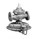
- Ontlastkleppen/bypass -kleppen: wanneer de systeemdruk buitensporig hoog wordt, openen ontlastkleppen of bypass -kleppen automatisch om druk, beschermingsapparatuur en leidingen te beschermen.
- Uitvoering van noodsituaties: in bepaalde processen die noodlucht moeten ontluchten, zorgt fail-open ervoor dat het medium snel kan worden ontslagen.
Faallust (fl) / fail-in-place
Wanneer het aandrijfvermogen wordt onderbroken, blijft de regelklep in de laatste positie voordat de storing plaatsvond. Deze modus vereist meestal extra vergrendelingsmechanismen of energieopslagapparaten om de kleppositie te behouden. Dit wordt meestal bereikt door speciale positioners (met vergrendelingskleppen) of dubbelwerkende actuatoren in combinatie met energieopslagapparaten (zoals luchttanks of hydraulische sloten). Voor pneumatische systemen kunnen luchttanks een back-upluchtbron op korte termijn bieden voor dubbelwerkende actuatoren, waardoor ze specifieke acties kunnen onderhouden of voltooien wanneer de hoofdluchtbron faalt.
Typische toepassingsscenario's zijn onder meer:
- Systemen die handmatige interventie vereisen: in bepaalde complexe of gevoelige processen kunnen onmiddellijk volledig openen of sluitende kleppen leiden tot ernstiger gevolgen. Fail-Safe-werking stelt operators de tijd in staat om de situatie te beoordelen en handmatig in te grijpen, waardoor het systeem veilig in een stabiele toestand wordt gebracht.
- Het handhaven van de huidige status: in niet-noodscenario's waarbij het handhaven van stroom noodzakelijk is, zoals wanneer stroomschommelingen minimaal effect hebben op stroomafwaartse processen, kan faalveilige werking onnodige procesonderbrekingen voorkomen.
- Regelgeving met een hoge precisie: in circuits die een zeer nauwkeurige verordening vereisen, voorkomt dat faalveilige werking kleppen plotseling volledig openen of sluiten wanneer signalen verloren gaan, waardoor de impact op het proces wordt verminderd.
Selectieprincipes
De selectie van een fail-safe-modus is niet willekeurig, maar is gebaseerd op een uitgebreide risicobeoordeling van het specifieke proces. Ingenieurs moeten analyseren welke klepstatus (gesloten, open of onderhouden) het risico op persoonlijk letsel, schade aan apparatuur en milieuvervuiling kunnen minimaliseren in het geval van een energiefout. Bovendien moeten factoren zoals vloeistofeigenschappen (ontvlambaar, explosief, corrosief), de dynamische respons van het proces en in elkaar grijpende relaties met stroomopwaartse en stroomafwaartse apparatuur worden overwogen. Voor media die bijvoorbeeld gevaarlijke accumulatie kunnen veroorzaken, wordt de standaardpositie doorgaans geselecteerd als mislukt gesloten; Voor systemen die continu koeling of drukverlichting vereisen, wordt de standaardpositie geselecteerd als fail-open. Het naleven van relevante industrienormen en -voorschriften (zoals API, NFPA, IEC 61508) is ook van cruciaal belang, omdat deze normen vaak aanbevelingen of verplichte vereisten bieden voor faalveilige modi op basis van specifieke toepassingen.
De selectie van foutveilige modi is de "eerste lijn van verdediging" in procesveiligheidsontwerp. De vooraf ingestelde foutmodi van kleppen bepalen het "standaard" gedrag van het systeem onder worst-case omstandigheden. Dit vooraf ingestelde gedrag moet aansluiten bij de inherente gevaren van het proces om ervoor te zorgen dat het systeem in het geval van een fout automatisch de veiligste fysieke toestand binnengaat. De FC FC voorkomt bijvoorbeeld ongecontroleerde verbranding, terwijl de koelklep voor oververhitting explosies voorkomt. Dit belichaamt het principe van "veiligheid door ontwerp" in plaats van alleen te vertrouwen op post-incident remedies. Het onderstreept het belang van het uitvoeren van gedetailleerde analyses voor gevaren en operabiliteit (HAZOP) en veiligheidsintegriteitsniveau (SIL) beoordelingen van de processtroom tijdens de vroege stadia van een project. Leveranciers van controleklep zoalsXiangjing CompanyVolg diepgaande discussies met klanten over hun proceskenmerken bij het verstrekken van producten, en biedt professionele aanbevelingen voor fail-safe modus selectie in plaats van alleen standaardproducten te verkopen.
Deel twee: kerncomponenten voor het bereiken van fail-safe functionaliteit
Deze sectie biedt een gedetailleerde uitleg van de belangrijkste componenten voor faalveilige werking van aandrijfregelkleppen-actuatoren en kleppositioners-en analyseren hun respectieve werkprincipes, faalveilige mechanismen, voordelen en nadelen en toepassingen in de industrie.
1. Actuatoren: rijdende faalveilige acties
Actuatoren zijn de "spieren" van regelkleppen, verantwoordelijk voor het omzetten van besturingssignalen in mechanische beweging om de positie van het stroomherstelelement van de klep te wijzigen. Hun ontwerp bepaalt direct het gedrag van de klep tijdens een fout. Actuatoren worden meestal onderverdeeld in drie hoofdtypen: pneumatisch, elektrisch en hydraulisch.
Pneumatische actuators
Pneumatische actuatoren gebruiken perslucht (typisch lucht) druk om een zuiger of diafragma aan te drijven, waardoor de klepsteel naar voren en naar achteren beweegt (lineaire beweging) of draait via een versnellingsbak. Gasdruk kan afwisselend worden toegepast op beide zijden van de zuiger (dubbelwerkend) of slechts één kant invoeren en op een veer afhankelijk zijn voor terugkeer (single-acting).
Fail-safe mechanismen:
- Spring-return: dit is het meest voorkomende en inherente faalveilige mechanisme bij pneumatische actuatoren. Wanneer de aandrijfluchtbron verloren gaat, duwt de vooraf gecomprimeerde voorjaarskracht de actuator naar een vooraf ingestelde veilige positie (volledig open of volledig gesloten), dit ontwerp is eenvoudig en betrouwbaar, veel gebruikt in toepassingen die een duidelijke faalveilige status vereisen.
- Luchttank/accumulator: voor dubbelwerkende pneumatische actuatoren, wanneer de hoofdluchttoevoer mislukt, kan de aangesloten luchttank back-up gecomprimeerde lucht bieden, waardoor de klep kan blijven werken of de vooraf ingestelde faalveilige actie binnen een specifiek tijdsbestek kan voltooien. Dit is met name handig voor het handhaven van procesbewerkingen of veilige afsluitingen gedurende een langere periode, zoals ervoor zorgen dat een regelklep blijft werken tijdens een specifiek tijdsbestek na een storing in de luchtcompressor, waardoor reparaties of veilige afsluiting mogelijk zijn.
Voordelen en nadelen:
- Voordelen: eenvoudige structuur, lichtgewicht en relatief eenvoudig te installeren en te onderhouden. Het werkmedium is lucht, wat gemakkelijk uit te putten, milieuvriendelijk en kosteneffectief is. Uitgangskracht en bedrijfssnelheid zijn gemakkelijk instelbaar, met typisch snelle responstijden. Hoge betrouwbaarheid en lange levensduur. Fire proof, explosiebestendig en vochtbestendig, geschikt voor omgevingen op hoge temperatuur. Kan energie opslaan, waardoor gecentraliseerde luchttoevoer en overdracht op lange afstand mogelijk is.
- Nadelen: vanwege de samendrukbaarheid van lucht, wordt de bedrijfssnelheid gemakkelijk beïnvloed door belastingveranderingen en is lage snelheidsstabiliteit inferieur aan hydraulische cilinders. Uitgangskracht is over het algemeen lager dan die van hydraulische cilinders. Langzame pneumatische signaaltransmissiesnelheid, ongeschikt voor complexe systemen die een snelle signaaltransmissie vereisen. Vereist een continue toevoer van perslucht en regelmatig onderhoud om lekken te voorkomen. De initiële kosten kunnen lager zijn, maar langdurige operationele kosten (compressoren, leidingen, onderhoud) kunnen hoger zijn.
Industriële toepassingen: veel gebruikt in toepassingen die snelle bewegingen en explosieverdichte vereisten vereisen, zoals de petroleum en aardgas, chemische, voedsel en drank en waterbehandelingsindustrie.
Elektrische actuators
Elektrische actuatoren zetten elektrische energie om in rotatie- of lineaire beweging met behulp van motoren (gewoonlijk stepper -motoren en servomotoren) om positie, snelheid, koppel, enz. Beheersing te regelen, enz. Rezen nauwkeurige positionering door pulsen, terwijl servomotoren dynamische respons bereiken door feedbackbesturing.
Fail-safe mechanismen:
- Back-upvermogen/condensator: in het geval van een hoofdvermogenstoring kunnen elektrische actuatoren worden uitgerust met een back-upbatterij of supercondensator om tijdelijk vermogen te bieden om vooraf ingestelde faalveilige acties te voltooien (zoals het rijden van de klep naar de volledig open of volledig gesloten positie). Dit mechanisme zorgt voor de uiteindelijke veiligheidsbarrière in het geval van een stroomstoring.
- Mechanische veer: sommige elektrische actuatoren bevatten ook mechanische veren, die de veerkracht gebruiken om de klep naar een veilige positie te duwen in het geval van een stroomuitval. Dit ontwerp combineert de precieze regeling van elektrische stroom met de inherente faalveilige kenmerken van veren.
Voordelen en nadelen:
- Voordelen: biedt nauwkeurige en herhaalbare positionering, waardoor het ideaal is voor geautomatiseerde taken. Hoge energie -efficiëntie, vooral in statische belastingtoepassingen waar minder energie wordt geconsumeerd. Lage onderhoudsonderhoud, minder onderdelen en geen vloeistofsystemen. Hoge veelzijdigheid, in staat om zich aan te passen aan verschillende omgevingen, en gemakkelijk te programmeren voor complexe bewegingspatronen. Rustige operatie. In staat om een zeer nauwkeurige positionering en verstelbare bewegingssnelheden te bereiken. Rotatiesnelheid wordt niet beïnvloed door belastingsvariaties en is onafhankelijk van de voedingspanning en frequentie. In staat tot afstandsbediening.
- Nadelen: kosten zijn meestal hoger dan pneumatische actuatoren. Besturingssystemen zijn complex en vereisen gespecialiseerde kennis voor installatie en onderhoud. Omgevingsweerstand (bijv. Waterdichting, stofbestrijding) kan lager zijn dan pneumatische componenten. Uitgangskracht is relatief klein, ongeschikt voor zware taken. Afhankelijk van een stabiele voeding en is mogelijk niet geschikt voor explosieve omgevingen (tenzij speciaal ontworpen). Cyclustijd kan langzamer zijn dan pneumatische systemen.
Industriële toepassingen: geschikt voor scenario's die een precieze controle en flexibele werking vereisen, zoals robotwarmaandrijvingen, aanpassingen van transportbanden, assemblagelijnen, landbouwmachines, ventilatiesystemen, zonnestelsels, materiaalbehandeling en reinigingsapparatuur. Ook veel gebruikt bij stroomopwekking, waterbehandeling en farmaceutische industrie.
Hydraulische actuators
Hydraulische actuatoren gebruiken onder druk staande hydraulische vloeistof (meestal olie) om zuigers of bladen aan te drijven, waardoor vloeistofdruk omzet in mechanische beweging. De niet -samendrukbaarheid van hydraulische vloeistof stelt het in staat om enorme kracht te bieden.
Fail-safe mechanismen:
- Spring-return: vergelijkbaar met pneumatische systemen, kunnen hydraulische actuatoren ook veren opnemen om de klep naar een vooraf ingestelde veilige positie te duwen met behulp van veerkracht wanneer het hydraulische systeem druk verliest. Deze methode wordt vaak gebruikt in noodtoepassingen die snelle uitschakeling of opening vereisen.
- Hydraulische vergrendeling: door het hydraulische oliecircuit te vergrendelen, blijft de actuator in zijn laatste positie wanneer de druk verloren gaat. Dit wordt meestal bereikt door speciale klepontwerpen (zoals tweeposities, tweerichtingsmagneetkleppen), zodat de zuigeruitgangsstang op zijn plaats wordt vergrendeld tijdens vermogens- of signaalonderbrekingen om de verstoring van het systeem te voorkomen.
Voordelen en nadelen:
- Voordelen: in staat om extreem hoog koppel/stuwkrachtuitgang te produceren, geschikt voor het bedienen van grote, zware of hogedrukkleppen. Positionering met een hoge precisie maakt een nauwkeurige procescontrole mogelijk. Quick-respons op bedieningssignalen, geschikt voor ESD (Emergency Shutdown System) en kleptoepassingen die snelle actie vereisen. Robuust en duurzaam ontwerp met relatief lage onderhoudsbehoeften en een lange levensduur.
- Nadelen: complex systeem dat hydraulische pompen, reservoirs, leidingen, enz. Vereist, wat resulteert in hoge installatie- en onderhoudskosten. Risico op hydraulische vloeistoflekkage, die het milieu kan verontreinigen of veiligheidsproblemen kan veroorzaken. Hoge vereisten voor vloeistof netheid; Vloeistofverontreiniging kan leiden tot storingen.
Industriële toepassingen: voornamelijk gebruikt in zware taken die een hoge krachtproductie en snelle respons vereisen, zoals olie- en gasboorplatforms, waterkrachtcentrales, grote industriële machines en gaspijpleidingen.
De faalveilige kenmerken van een actuator zijn inherente eigenschappen, geen extra functies. Faalveilige mechanismen zoals voorjaarsrendement, luchtreservoirs en back-upvermogenbronnen worden niet toegevoegd als extra's bovenop de basisfuncties van de actuator, maar zijn inherente eigenschappen die vanaf het begin worden overwogen en geïntegreerd in het ontwerp. De lente -terugkeer maakt bijvoorbeeld gebruik van potentiële energie, terwijl luchtreservoirs de samendrukbaarheid van gas gebruiken om energie op te slaan. Deze mechanismen worden passief geactiveerd in het geval van energiefalen, waardoor de "passieve veiligheid" ontwerpfilosofie wordt belichaamd. Dit betekent dat bij het selecteren van regelkleppen zich niet alleen moet concentreren op het rijcapaciteit van de actuator, maar ook grondig begrijpen of de ingebouwde faalveilige mechanismen aan de specifieke vereisten van het proces voldoen.Xiangjing CompanyBiedt gedetailleerde uitleg over de faalveilige principes van verschillende actuatoren bij het aanbieden van controleklepoplossingen, waardoor klanten de meest geschikte producten voor hun toepassingsscenario's kunnen selecteren en de betrouwbaarheid onder extreme omstandigheden waarborgen.
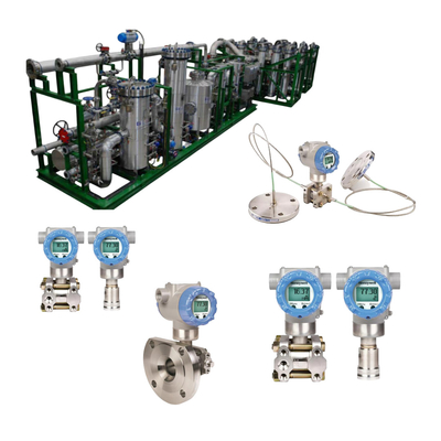
2. Kleppositieer: precieze controle- en foutdiagnose
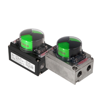
Een kleppositioner is een kritiek accessoire in een regelklepassemblage. Het zorgt er niet alleen voor dat de klep precies reageert op het regelen van signalen, maar ook een sleutelrol speelt bij het verbeteren van de betrouwbaarheid van regelkleppen en het mogelijk maken van geavanceerde foutdiagnose.
De functie en het belang van kleppositioners
De kernfunctie van een positioner is om onder druk staande lucht (of elektriciteit) aan de klepactuator te leveren, zodat de positie van de klepsteel of klepas nauwkeurig aansluit bij het setpoint van het besturingssysteem. Dit wordt bereikt door de werkelijke kleppositie te vergelijken met de gewenste kleppositie en de nodige aanpassingen te maken. De positioner overwint factoren zoals klepsteelpakking wrijving, actuatorvertraging en onevenwichtige krachten op de klepstekker die de precieze kleppositionering beïnvloeden, waardoor het wordt verbeterd
De regelsnauwkeurigheid en responssnelheid van de regelklep. Bovendien vereist de positioner meestal positiefeedback van de klepstam of klepas en verzendt de kleppositiestatus naar het bovenste niveau-systeem voor procesmonitoring, foutdiagnose of start/stop verificatie.
Signaaltypen en feedbackmechanismen
Regelkleppen ontvangen signalen van controllers om te werken.
- Pneumatische signalen: traditionele procesapparatuur maakt gebruik van pneumatische druksignalen (meestal 20,7 tot 103 kPa of 3 tot 15 psig) als besturingsinstelling voor regelkleppen om de klep van 0% naar 100% positie te verplaatsen.
- Analog I/P-signaal (4-20 mA): de meeste moderne procesapparatuur maakt gebruik van een 4 tot 20 ma DC-signaal om regelkleppen te reguleren. De I/P -converter in de positioner zet het elektronische stroomsignaal om in een pneumatisch druksignaal. Het voordeel van het 4-20 MA-signaal ligt in zijn sterke ruisimmuniteit, weerstand tegen spanningsdruppels en zelfmonitoringcapaciteit (stroom onder 3,8 mA of boven 20,5 mA wordt beschouwd als een fout).
- Digitaal signaal: digitale klepcontrollers zijn op microprocessor gebaseerde instrumenten die via digitale signalen communiceren met het besturingssysteem. Gemeenschappelijke digitale communicatieprotocollen omvatten HART® (bedekt op het traditionele 4-20 MA-signaal), Foundation ™ Fieldbus en Profibus. Draadloze technologie biedt ook een alternatieve methode voor het verzenden van informatie.
- Feedbackmechanisme: positioners vereisen positiefeedback van de klepsteel of klepas om de klep nauwkeurig te regelen.
- Mechanische feedback: In traditionele pneumatische positioners wordt de positie van de klepstam/as vergeleken met de positie van de balg die het pneumatische besturingssignaal ontvangt via mechanische koppelingen en nokken. Deze methode heeft nadelen zoals hoge slijtage, lage nauwkeurigheid en korte levensduur.
- Elektronische feedback: de microprocessor in een digitale klepcontroller ontvangt elektronische feedback op de kleppositie. Hall-effectsensoren worden bijvoorbeeld gebruikt om de magnetische velddichtheid op een permanente magneetarray te meten, waardoor feedback van staafloze, contactloze klep stengelpositie mogelijk is. Dit elimineert problemen zoals slijtage, corrosie en trillingen, waardoor stabiliteit en betrouwbaarheid aanzienlijk wordt verbeterd.
Kleppositie-typen en hun rol in faalveilige werking
- Pneumatische positioners:
- Kenmerken: ontvang pneumatische signalen en uitvoerluchtdruk om de actuator te reguleren. Eenvoudig ontwerp, lage kosten en betrouwbare werking.
- Rol in fail-safe werking: geschikt voor eenvoudige, robuuste bewerkingen, vooral in omgevingen zonder stroomvoorziening of met explosierisico's, omdat ze geen vonken produceren. Ze kunnen voldoende kracht bieden om kleppen te sluiten.
- Elektro-pneumatische positioners / analoge I / P-positioners:
- Kenmerken: ontvang elektrische signalen (meestal 4-20 mA), converteer ze in pneumatische signalen via een I/P-converter en voer ze uit naar de actuator. In vergelijking met pure pneumatische positioners bieden ze een hogere precisie en resolutie.
- Rol in fail-safe werking: combineer de precisie van elektrische controle met de robuustheid en veiligheid van pneumatische werking. Geschikt voor industriële omgevingen met zowel elektrische als pneumatische infrastructuur, evenals complexe controlestrategieën die een hogere precisie vereisen.
- Digitale/slimme positioners:
- Functies: Ingebouwde microprocessor die in staat is om digitale signalen te ontvangen (bijv. Hart, Foundation Fieldbus, Profibus) of 4-20MA-signalen. Biedt een hoge precisie, hoge resolutie, hoge betrouwbaarheid en geavanceerde diagnostische en communicatiefuncties.
- Rol in fouttolerantie:
- Geavanceerde diagnostiek: in staat tot realtime monitoring van klepprestaties, het detecteren van anomalieën zoals klepstokken, lekkage, verpakkingskleding en lenteveroudering. Dit maakt een verschuiving van gepland onderhoud naar voorspellend onderhoud mogelijk, waardoor de algemene foutveiligheid van het systeem aanzienlijk wordt verbeterd.
- Zelfkalibratie en monitoring op afstand: veel slimme positioners hebben zelfkalibratie en monitoringmogelijkheden op afstand, het vereenvoudigen van installatie en inbedrijfstelling, het verlagen van onderhoudskosten en het mogelijk maken van veilige werking in gevaarlijke gebieden.
- Contactloze feedbacktechnologie: gebruik van niet-contact feedback-technologieën zoals Hall Effect-sensoren elimineert slijtage, corrosie en trillingsproblemen die verband houden met traditionele mechanische koppelingen en potentiometers van het contacttype. Dit verbetert fundamenteel de nauwkeurigheid en betrouwbaarheid van feedback van de kleppositie, waardoor de prestaties van de foutveilige verder worden verbeterd.
Positioners zijn de sleutel tot de "intelligentie" en "voorspellende veiligheid" van regelkleppen. Vroege positioners hebben voornamelijk niet -lineaire problemen in actuatoren aangepakt om een precieze kleprespons op bedieningssignalen te garanderen. Met technologische vooruitgang, met name in microprocessor- en sensortechnologieën, bereiken digitale positioners niet alleen een precieze controle, maar bewaken ze ook de klepgezondheid in realtime via ingebouwde diagnostische algoritmen en communicatieprotocollen. Dit stelt systemen in staat om over te schakelen van "passief reageren op fouten" om "actief te voorspellen en te voorkomen, fouten", die de veiligheidsniveaus van de fout aanzienlijk verbeteren. Deze evolutie van 'controle' tot 'diagnose' tot 'voorspelling' vormt een belangrijke trend in apparatuurbeheer onder het industriële 4.0 -raamwerk. Investeren in slimme positioners gaat niet alleen over het verbeteren van de controle -nauwkeurigheid van regelkleppen; Het is een investering in de "gezondheidsmonitoring" en "preventieve veiligheid" van de hele processtroom. De Smart Positioner -oplossingen van Xiangjing Company kunnen klanten helpen hogere niveaus van foutdiagnose en voorspellend onderhoud te bereiken, waardoor het risico op niet -geplande downtime wordt verminderd en de algehele operationele efficiëntie en veiligheid van de fabriek wordt verbeterd.
Deel drie: geavanceerde faalveilige strategieën en technologieën
Naast faalveilig ontwerp voor individuele regelkleppen zijn geavanceerde veiligheidsstrategieën vereist in kritieke processen, zoals overbodig ontwerp, geavanceerde foutdiagnose, voorspellend onderhoud en overwegingen voor speciale bedrijfsomstandigheden.
1. Redundant ontwerp- en veiligheidslussen
Om de veiligheid en beschikbaarheid van het systeem verder te verbeteren, vooral bij het hanteren van een hoog risico- of hoogwaardige media, is redundant ontwerp een onmisbare strategie.
Soorten redundante configuraties
- 1OO2 (één-out-of-twee) serie Configuratie: twee regelkleppen zijn geïnstalleerd in serie. Als een klep of het besturingssignaal mislukt, wordt het hele systeem uitgeschakeld om verdere schade te voorkomen. Deze configuratie verbetert de veiligheid aanzienlijk, omdat elke klepstoring een veilige afsluiting veroorzaakt. Het wordt vaak gebruikt in mediatransportlijnen die hogere veiligheidsniveaus vereisen.
- 2OO2 (twee-out-of-twee) parallelle configuratie: twee regelkleppen zijn parallel geïnstalleerd. Als een klep of het besturingssignaal mislukt, blijft het systeem actief en blijft het werken. Deze configuratie verbetert voornamelijk de beschikbaarheid van het systeem, zodat het proces niet wordt onderbroken in het geval van een enkele componentstoring. Het wordt vaak gebruikt in scenario's die een hoge beschikbaarheid vereisen, zoals koellussen.
- 2OO3 (twee-out-of-three) Stemconfiguratie: deze configuratie combineert hogere veiligheid en beschikbaarheid. Het systeem heeft drie regelkleppen en het systeem voert alleen de overeenkomstige actie uit wanneer twee van de kleppen hetzelfde signaal verzenden. Dit maakt het mogelijk om de functionaliteit van een enkele klep te testen zonder de actuator te activeren, terwijl het systeem veilig kan blijven werken, zelfs als een enkele klep mislukt. De 2OO3 -functionele module combineert series en Namur -technologie om het hoogste niveau van veiligheid en betrouwbaarheid te bieden, en maakt onderhoud mogelijk tijdens de werking.
Toepassing in veiligheidsinstrumenten Systems (SIS)
Redundant Design is een cruciaal onderdeel van Safety Instrumented Systems (SIS). SIS vormt een onafhankelijke beschermende laag door sensoren, logische controllers en uiteindelijke besturingselementen (zoals regelkleppen), met als doel het proces in een veilige toestand te brengen wanneer het basisprocescontrolesysteem (BPC's) faalt. Redundante regelkleppen zorgen voor de uiteindelijke uitvoeringsmogelijkheden van SIS en voldoet aan specifieke SIL -niveau -vereisten.
Redundant Design is een kunst van het balanceren van veiligheid en beschikbaarheid. Redundante architecturen zoals 1OO2, 2OO2 en 2OO3 gaan niet alleen over het vergroten van het aantal apparaten, maar omvatten strategische keuzes tussen "veiligheid" (voorkomende gevaren) en "beschikbaarheid" (handhavende werking) op basis van verschillende procesvereisten. 1OO2 geeft prioriteit aan veiligheid boven de beschikbaarheid, 2OO2 geeft prioriteit aan de beschikbaarheid boven de veiligheid, terwijl 2OO3 de optimale balans tussen de twee probeert te vinden. Deze afweging weerspiegelt de diepe overwegingen in complex systeemontwerp: hoe optimaal risicobeheer en operationele efficiëntie binnen beperkte middelen te bereiken. Dit betekent dat bij het selecteren van redundantiestrategieën, bedrijven een duidelijk inzicht moeten hebben in het risiconiveau van hun procesactiviteiten, downtime -kosten en veiligheidseisen. Xiangjing Company kan, als professionele leverancier van regelkleppen, producten en technische ondersteuning bieden die zijn afgestemd op verschillende redundantie -architecturen, waardoor klanten de meest geschikte veiligheidslussen ontwerpen en implementeren op basis van hun specifieke behoeften, waardoor het optimale evenwicht tussen veiligheid en beschikbaarheid wordt bereikt.
2. Foutdiagnose en voorspellend onderhoud
Alleen foutveilige mechanismen hebben is onvoldoende. Het vermogen om potentiële fouten in realtime te diagnosticeren en te voorspellen, waardoor het tussenkomen voordat een fout optreedt, is een vereiste op een hoger niveau voor het verbeteren van de betrouwbaarheid van de regelklepsystemen.
Diagnostische functies van intelligente positioners
- Klepstokkendetectie: bewaakt de afwijking tussen feedback van de kleppositie en het setpoint om te bepalen of het plakken is opgetreden.
- Lekdetectie: bewaakt de geschiktheid van de uitvoerluchtdruk via druksensoren om interne of externe lekken te diagnosticeren.
- Verpakkingsslijtage diagnose: bewaakt veranderingen in maximale wrijvingskracht om de veroudering of verharding van de pakking van de klier te bepalen.
- Spring veroudering/kantel: gebruikt krachtbalansdiagnose om abnormale aandoeningen in de actuatorveer te detecteren.
- Luchtcircuitdiagnose: detecteert de ernst van olie- en wateraccumulatie in de positioner.
- Bedrijfstijd/cyclustelling: Records Valve -bedrijfsgegevens om slijtniveaus te beoordelen.
Overgang van gepland onderhoud naar op staat gebaseerd onderhoud
Traditionele onderhoudsmodellen zijn gebaseerd op op tijd gebaseerd gepland onderhoud, wat kan leiden tot overbehoud of onderhoud onderhoud. Door gebruik te maken van realtime diagnostische gegevens van slimme positioners, kunnen fabrieken overstappen van tijdgebaseerd onderhoud (TBM) naar op conditie gebaseerd onderhoud (CBM) en voorspellend onderhoud (PDM). Dit betekent dat interventies alleen worden uitgevoerd wanneer apparatuurconditie de noodzaak van onderhoud aangeeft, waardoor onderhoudsbronnen worden geoptimaliseerd, onderhoudskosten wordt verlaagd en ongeplande downtime wordt geminimaliseerd. Bovendien elimineert de acceptatie van niet-contact klepspositie van de klep van de kleppositie zoals Hall Effect-sensoren problemen met betrekking tot slijtage, corrosie en trillingen geassocieerd met mechanische koppelingen en potentiometers van het contacttype, het fundamenteel verbeteren van de nauwkeurigheid en betrouwbaarheid van feedback en het bieden van een gegevensstichting voor precieze diagnostics.
Gegevensgestuurd voorspellend onderhoud vertegenwoordigt een sprong van "reactief" naar "proactieve" foutveiligheid. Traditionele foutveiligheid wordt passief geactiveerd nadat een fout is opgetreden, terwijl geavanceerde diagnostische technologieën realtime gegevensanalyse gebruiken om waarschuwingen te geven in de "beginnende" fase van een fout. Dit stelt onderhoudspersoneel in staat om reparaties te plannen zonder de productie te verstoren, waardoor potentiële "foutveiligheidsgebeurtenissen" worden omgezet in "geplande onderhoudsgebeurtenissen", waardoor de daadwerkelijke activering van foutveiligheidsmechanismen wordt vermeden en de veiligheidsrisico's en downtime -verliezen wordt verminderd. Dit vormt een belangrijke vooruitgang in industriële automatisering, die overstaat van "reactief" naar "proactieve" benaderingen. Investeren in slimme positioners gaat niet alleen over verbeteren
Nauwkeurigheid van de controleklepbeheersing, maar ook over investeren in de "gezondheidsmonitoring" en "preventieve veiligheid" van het hele proces. De Smart Positioner -oplossingen van Xiangjing Company helpen klanten om geavanceerde foutdiagnose en voorspellend onderhoud te stellen, waardoor het risico op ongeplande downtime wordt verminderd en de algehele operationele efficiëntie en veiligheid van de fabriek wordt verbeterd.
3. Fail-veilige overwegingen onder speciale bedrijfsomstandigheden
Onder extreme of speciale bedrijfsomstandigheden vereist faalveilig ontwerp van regelkleppen aanvullende overweging om media-eigenschappen en milieu-uitdagingen aan te pakken.
Omgevingen op hoge temperatuur en lage temperatuur
Extreme temperaturen kunnen ervoor zorgen dat klepcomponenten uitzetten, samentrekken, bros worden of verzachten, wat de normale klepwerkzaamheden en afdichtingprestaties beïnvloedt. Hoge temperaturen kunnen bijvoorbeeld de klepstekker in beslag nemen, terwijl lage temperaturen de prestaties van de actuator kunnen beïnvloeden. Oplossingen omvatten het gebruik van een uitgebreide klepbonnet om de klepstamverpakking te beschermen tegen extreme temperaturen en het selecteren van speciale hoge temperatuur of lage temperatuur resistent materialen om de betrouwbaarheid binnen het ontwerptemperatuurbereik te waarborgen.
Corrosieve, high-viscositeitsmedia
Corrosieve media kunnen kleplichamen en interne componenten eroderen, terwijl media met een hoge viscositeit kunnen hechten aan klepstelen, waardoor ze tussen de stengel en het lichaam stammen, waardoor verdere werking moeilijk wordt. Oplossingen zijn onder meer het gebruik van corrosiebestendige materialen (zoals speciale legeringen) en het optimaliseren van de interne componentstructuren van de klep om media-hechting en schaalverdeling te verminderen. V-poortrotatie
Regelkleppen hebben voordelen bij het omgaan met vaste stoffen.
Speciale vereisten voor noodafsluitingskleppen (ESD -kleppen)
Uitschikkleppen (ESD -kleppen) zijn kritieke componenten in veiligheidsinstrumentiesystemen, waarbij de primaire taak om het proces snel in een veilige toestand te brengen tijdens noodsituaties. ESD -kleppen vereisen meestal een extreem hoge betrouwbaarheid, snelle sluitingssnelheid en lage lekkages. Ze zijn vaak ontworpen als "fail-closed" of "fail-safe" om te zorgen voor onmiddellijke vloeistofuitsluiting wanneer de aandrijfsenergie wordt onderbroken. Om de betrouwbaarheid van ESD -kleppen te waarborgen, zijn de klepsluitingsschakelaars of kleplekdetectiesystemen meestal vereist. De sluitingsschakelaar van de sluiting wordt geactiveerd nadat de klep volledig is gesloten, waardoor de brandstofveiligheidsafsluiter volledig is gesloten vóór de zuiverings- en ontstekingscyclus. Het kleplekdetectiesysteem monitoren lekken door de pijpleiding tussen twee afsluitingskleppen onder druk te zetten of individuele kleplekken te bepalen via drukschakelaarsignalen.
Faalveilig ontwerp moet diep worden geïntegreerd met de operationele omgeving. Het simpelweg selecteren van de juiste fail-safe-modus is onvoldoende, omdat de werkelijke werkomgeving van de regelklep (temperatuur, middelgrote eigenschappen, druk, enz.) Een beslissende impact kan hebben op de faalveilige prestaties. Corrosieve media kunnen bijvoorbeeld falen van klepcomponenten veroorzaken, waardoor het fail-safe mechanisme onbruikbaar is.
Daarom moet faalveilig ontwerp systematisch zijn, rekening houdend met de uitdagingen van de bedrijfsomstandigheden van materiaalselectie, structureel ontwerp, tot diagnostisch onderhoud. Dit betekent dat standaardregelkleppen mogelijk niet voldoen aan de veiligheidseisen onder extreme bedrijfsomstandigheden, waardoor aangepaste of speciaal ontworpen oplossingen nodig zijn.Xiangjing CompanyHet gebruik van zijn uitgebreide expertise in regelkleppen, kan professionele selectieaanbevelingen en aangepaste producten bieden die zijn afgestemd op verschillende speciale bedrijfsomstandigheden, zodat ervoor zorgt dat regelkleppen op betrouwbare wijze faalveilige functies uitvoeren, zelfs in de meest veeleisende omgevingen.
Deel vier: Case studies van faalveilige regelkleptoepassingen in de industrie
Faalveilig ontwerp van regelkleppen speelt een onmisbare rol in veel industriële velden. De volgende zijn verschillende typische industrieën en hun specifieke toepassingen.
1. Olie- en gasindustrie
In stroomopwaartse olie- en gaswinning moeten regelkleppen in putkop-regelsystemen nauwkeurige stroomregeling en nooduitsluitingscapaciteiten behouden onder extreme druk, corrosieve omgevingen en temperatuurschommelingen. Belangrijkste functies van wellhead -regelkleppen zijn onder meer throttlingcontrole, drukregelgeving en noodafsluiting.
Bij het transport van olie en gaspijpleiding worden regelkleppen gebruikt om stroom, druk en temperatuur te reguleren. Emergency-sluitingskleppen (ESD) kunnen snel sluiten wanneer onveilige omstandigheden worden gedetecteerd, zoals pijpleidingsbreuken of abnormale druk, om de lekkage van hoogwaardige en gevaarlijke stoffen te voorkomen, waardoor milieuvervuiling en belangrijke veiligheidsongevallen worden vermeden. In brandertoepassingen in raffinaderijen en chemische fabrieken vereisen brandstofgaskleppen doorgaans "fail-clos" functionaliteit om ervoor te zorgen dat de brandstoftoevoer onmiddellijk wordt afgesneden in het geval van stroomuitval of signaalverlies, waardoor branden en explosies worden voorkomen. Industriestandaarden vereisen typisch de installatie van twee direct verbonden afsluitkleppen om een redundante bescherming te bieden.
2. Chemische en farmaceutische industrie
Nauwkeurige temperatuur- en drukregeling zijn van cruciaal belang in chemische reactoren. Koelwaterkleppen worden bijvoorbeeld vaak ontworpen als "fail-open" om ervoor te zorgen dat koelwater blijft stromen in het geval van een koelsysteemfout, waardoor de weggelopen reactortemperatuur en potentiële explosies worden voorkomen. Voed kleppen worden vaak ontworpen als "fail-closed" om de materiaaltoevoer onmiddellijk af te snijden in het geval van een weggelopen reactie.
De chemische en farmaceutische industrie verwerken vaak corrosieve, brandbare, explosieve of giftige media. Het faalveilige ontwerp van regelkleppen zorgt ervoor dat gevaarlijke media veilig kunnen worden geïsoleerd of naar een veilig gebied kunnen worden gericht in het geval van een lek, abnormale druk of systeemfalen. Regelkleppen die worden gebruikt voor media met een hoge viscositeit vereisen bijvoorbeeld een speciaal ontwerp om te voorkomen dat gemiddelde hechting de klepstokken veroorzaakt, waardoor de faalveilige werking kan worden aangetast. Bij farmaceutische productie zijn precieze stroomcontrole en nooduitsluitingscapaciteit van cruciaal belang voor productkwaliteit en productie van productie. De faalveilige kenmerken van regelkleppen zorgen voor nauwkeurigheid en herhaalbaarheid in processen zoals mengen, reactieconditie en productvulling.
3. Waterbehandeling en krachtindustrie
In waterzuiveringsinstallaties, dammen en irrigatienetwerken worden regelkleppen gebruikt om waterstroom, druk en vloeistofniveau te reguleren. Faalveilige kleppen zorgen ervoor dat in het geval van afwijkingen in het watervoorzieningssysteem, ze overmatige consumptie, balansstroomverdeling kunnen voorkomen of overstromingen in noodsituaties kunnen voorkomen. In het Harbin Mudanshan Water Supply Pipeline Project werden DN1600 VAG -zuigerkleppen bijvoorbeeld geïnstalleerd om de waterdruk en -stroom te regelen en de hoogtedrukverschillen te compenseren.
In energiecentrales worden regelkleppen gebruikt om kritieke processen zoals stoomstroom, koelwater en brandstoftoevoer te reguleren. Regelkleppen in koelsystemen worden meestal ontworpen als "fail-open" om te zorgen voor een continu koelwaterstroom in geval van pompfout of blokkering van de pijpleiding, waardoor oververhitting van apparatuur wordt voorkomen. Hydraulische actuatoren, met hun hoge koppelproductie en snelle responscapaciteit, worden vaak gebruikt om grote, zware of hogedrukkleppen te bedienen, zoals in waterkrachtcentrales en gaspijpleidingen.
Industrie-kenmerken bepalen de focus van faalveilige strategieën. Hoewel de kernprincipes van faalveilig universeel zijn, hebben verschillende industrieën aanzienlijke verschillen in hun vereisten en prioriteiten voor faalveilig. De olie- en gasindustrie geeft bijvoorbeeld prioriteit aan explosie en lekpreventie, dus FC-kleppen en redundante afsluitsystemen zijn kern; De waterbehandelingsindustrie kan prioriteit geven aan de continuïteit van de watervoorziening en overstromingspreventie, dus Fo -kleppen en stroomregelkleppen zijn belangrijker. Deze variabiliteit vereist dat leveranciers van controleklepklep het technisch begrip en aangepaste oplossingsmogelijkheden bezitten. Dit betekent dat de verkoop en toepassing van regelkleppen geen one-size-fits-all-aanpak zijn, maar een diep begrip vereisen van de industriële achtergrond van de klant en specifieke procesvereisten. Als een professionele oplossingsoplossingsoplossingen van de controleklep, moet Xiangjing Company de nadruk leggen op zijn uitgebreide ervaring en aangepaste mogelijkheden in meerdere industriële sectoren om klanten op maat gemaakte foutveilige oplossingen te bieden, waardoor het concurrentievermogen van de markt wordt verbeterd.
Deel vijf: de bijdragen en oplossingen van Xiangjing Company op het gebied van controleklep faalveilige technologie
Xiangjing Company, de officiële website, als toonaangevende onderneming in de controleklepindustrie, heeft zich altijd aan de filosofie van "Safety First, Innovation-Driven" gehouden, toegewijd aan het bieden van wereldwijde industriële klanten met uitstekende controleklepproducten en uitgebreide fail-safe-oplossingen.
Xiangjing Company is al vele jaren diep betrokken bij de controleklepindustrie en heeft een professioneel team bestaande uit ervaren ingenieurs, R & D -personeel en experts uit de industrie. Het bedrijf richt zich op het ontwerp, de productie, het testen en de toepassing van regelkleppen, het verzamelen van diepe technische expertise en uitgebreide praktische ervaring. Xiangjing Company begrijpt de cruciale rol van controlekleppen in de moderne productie en beschouwt ze als een essentieel onderdeel bij het verbeteren van de efficiëntie, veiligheid, winstgevendheid en milieubeschermingsmogelijkheden.
Xiangjing Company biedt een uitgebreid scala aan regelklepproducten, waaronder verschillende klepinstellingen, klepinteries, actuatoren en klepaccessoires, om te voldoen aan de diverse behoeften van industriële toepassingen. De producten van het bedrijf bevatten vanaf het begin faalveilige ontwerpprincipes:
- Diversified Actuators: Xiangjing Company biedt krachtige pneumatische, elektrische en hydraulische actuatoren, en biedt verschillende faalveilige opties zoals ingebouwde voorjaarsrendement, back-up voeding of hydraulisch slot, op maat gemaakt op verschillende toepassingsscenario's, zodat kleppen betrouwbaar kunnen overstappen naar veilige beveiligde posities in het geval van stroomuitval.
- Smart Valve Positioners: Xiangjing Company biedt geavanceerde digitale/slimme kleppositioners die niet alleen zorgen voor een precieze controle van regelkleppen, maar ook uitgebreide diagnostische functies integreren om de klepgezondheid in realtime te controleren, zoals het detecteren van klep, lekkage of verpakkingsslijtage. Dit stelt klanten in staat om voorspellend onderhoud te implementeren, waarbij potentiële problemen worden aangepakt voordat ze escaleren, waardoor de faalveilige betrouwbaarheid van het systeem aanzienlijk wordt verbeterd.
- Aangepaste klep internals: voor speciale bedrijfsomstandigheden zoals hoge temperatuur, lage temperatuur, corrosieve en high-viscositeitsmedia, biedt Xiangjing Company het interne ontwerp van de klep en materiaalselectie op maat. V-poorts roterende regelkleppen hebben bijvoorbeeld aanzienlijke voordelen bij het omgaan met vaste stoffen, zodat ervoor zorgt dat regelkleppen stabiele prestaties en betrouwbare faalveilige werking behouden, zelfs in harde omgevingen.
De faalveilige technologische voordelen van Xiangjing Company worden weerspiegeld:
- Naleving van internationale veiligheidsnormen: enkele van de controleklepproducten en -oplossingen van Xiangjing Company kunnen voldoen aan de internationale veiligheidsnormen (zoals IEC 61508 SIL -certificering), en voldoen aan de hoge vereisten van klanten voor functionele veiligheid.
- Volledige Lifecycle Services: het bedrijf biedt niet alleen hoogwaardige controleklepproducten, maar biedt ook volledige levenscyclusdiensten van selectieadvies, oplossingontwerp, installatie en inbedrijfstelling tot onderhoud na installatie en foutdiagnose. Het expertteam van Xiangjing Company kan professioneel advies geven over de selectie van foutveilige modus en oplossingen voor systeemintegratie op basis van de specifieke procesvereisten en risicobeoordelingen van klanten.
- Betrouwbaarheid en lange levensduur van het dienstverlening: de producten van Xiangjing Company staan bekend om hun uitzonderlijke productieprocessen en strikte kwaliteitscontrole, waardoor een hoge betrouwbaarheid en een lange levensduur van verschillende harde bedrijfsomstandigheden worden gewaarborgd, waardoor de operationele kosten en onderhoudsfrequentie van klanten worden verminderd.
Xiangjing Company heeft met succes veilige en betrouwbare oplossingen voor controleklep verstrekt voor klanten in meerdere industrieën, waaronder petrochemicaliën, stroomopwekking, waterbehandeling en metallurgie, waardoor ze de productie -efficiëntie helpen verbeteren en de operationele veiligheid garanderen. Xiangjing Company kijkt ernaar uit om samen te werken met meer ondernemingen om gezamenlijk uitdagingen aan te gaan op het gebied van industriële automatisering.
Ga naar de officiële website van het bedrijf voor meer informatie over de innovatieve technologieën van Xiangjing Company en uitstekende producten op het gebied van controleklep.www.shgongboshi.com.
Conclusie: toekomstige vooruitzichten voor fouttolerante regelkleppen
Fout-tolerant ontwerp van regelkleppen is een onmisbare hoeksteen van moderne industriële automatisering. Het beïnvloedt niet alleen de productie -efficiëntie en productkwaliteit, maar heeft ook direct invloed op de veiligheid van apparatuur en personeel. Van traditionele veerrichtingsactuatoren tot intelligente digitale positioners, fouttolerante technologie voor regelkleppen evolueert voortdurend om zich aan te passen aan steeds complexere industriële omgevingen en hogere veiligheidsnormen.
Vooruitkijkend zal de toekomst van fail-safe regelkleppen de volgende trends vertonen:
- Intelligentie en voorspellende mogelijkheden: met de ontwikkeling van het Internet of Things (IoT), big data en kunstmatige intelligentie -technologieën zullen toekomstige controlekleppen steeds intelligenter worden. Smart Positioners zullen niet alleen besturingsfuncties uitvoeren, maar ook dienen als 'gezondheidsbewakingscentra', met behulp van realtime gegevensanalyse en machine learning-algoritmen om potentiële fouten te voorspellen en nauwkeuriger voorspellend onderhoud mogelijk te maken, waardoor interventies worden ingegaan voordat fouten optreden en risico's minimaliseren.
- Hogere integratie en modulariteit: om de installatie te vereenvoudigen, de kosten te verlagen en de betrouwbaarheid te verbeteren, zullen de componenten van de regelklep in de richting van een hogere integratie en modulair ontwerp trend zijn. Fail-safe functies kunnen nauwer worden geïntegreerd in de klepvorm of actuator, het verminderen van externe verbindingen en het minimaliseren van potentiële faalpunten.
- Draadloos en extern management: draadloze communicatietechnologie zal meer wijdverbreid worden, waardoor monitoring, diagnose en werking van controle van externe VA mogelijk worden

 Uw bericht moet tussen de 20-3.000 tekens bevatten!